

Calibration of Loop Antennas |
|
|
| DESCRIPTION |
|
|
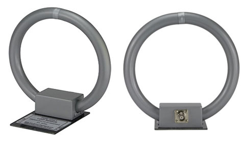
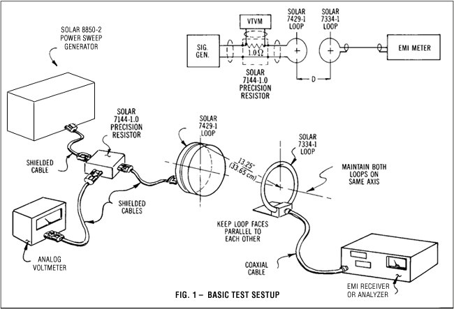
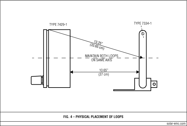
INTRODUCTION BASIC CONCEPT A specific RF current is established in the transmitting loop, measured with a series resistor and a voltmeter. At a given distance away, the field intensity generated by the current in the loop can be calculated. In the setup shown, for a distance of 13.25" (33.65 cm) from the periphery of the transmitting loop winding to the center of the receiving loop winding, the field intensity is calculated to be 178 volts-per-meter when a current of 1 A is flowing in the transmitting loop. SETUP DETAILS In setting up this dimension, take care to maintain the loops on the same axis and to orient them to face each other in a parallel fashion. A nonmetallic fixture should be used to maintain the proper physical conditions. The setup should be arranged so that no metallic objects are in the vicinity of the loop antennas. The signal generator and the EMI receiver should be at opposite ends of the setup so that the EMI receiver is not receiving the signal by some other path than by way of the Type 7334-1 loop. ELECTRICAL DETAILS When the physical dimension is maintained and the current through the loop is adjusted at each test frequency, the voltage received by the Type 7334-1 loop is measured with the EMI receiver. In most test locations there are strong magnetic fields at the power frequency and its harmonics. It is desirable to avoid these frequencies by using a very narrow bandwidth in the EMI receiver. A simple check on the validity of the received level would be to disconnect the signal generator from the transmitting loop. If the received signal is still present, the signal is arriving at the Type 7334-1 loop from some other source. DETERMINING LOOP FACTORS The field intensity in this setup is 177.83 volts-per-meter (165dB/µV/meter) which equates to 115.5 dB/pT. The measured level at each frequency in dB/µV is subtracted from 165 to obtain the correction factor for field intensity in dB with reference to one microvolt-per-meter (dB/µV/m). The measured level is subtracted from 115.5 to obtain the correction factor for field intensity in dB with reference to 1 pT (dB/pT). As an example, assume that the EMI receiver reading is 82 dB/µV at 10 kHz. Subtracting 82 from the 165 reference yields 83, the factor for field intensity in dB/ µV/m.
At this frequency, the 83 dB factor must be added to the EMI receiver reading to obtain the final answer in dB/µV/m.
When the answer is to be in dB/pT, derive the factor by subtracting the 82 dB in this example from 115.5 to yield a correction factor (in dB) of 33.5.
When using the Type 7334-1 loop in the RE01 or RE101 test, add the 33.5 correction to the EMI receiver reading (in dB) to obtain the field intensity expressed in dB/pT.
REFERENCE INFORMATION E = (47.15 N d2 l) ÷ D3
|
||||||||||||||||||||||||||||||||||||||||||||||||
 |
 |
|
|