Solar Electronics Company logo
SEC-logo

Using the Solar Type 7429-1 Loop Antenna

to establish magnetic field intensity

Type 7334-1 Loop Sensor
  DESCRIPTION top of page button
spacer

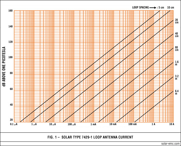
FORMULA FOR DETERMINING MAGNETIC FIELD INTENSITY
If we grind through the classic formula found on page 975 of Dr. Fred Terman's Radio Engineers Handbook (First Edition 1943) we find that the formula simplifies to:

Solar Type 7429-1 magnetic field formula

when using the dimensions of the Solar Type 7429-1 Loop and a distance of 5 cm as required by Test Method RS01 in MIL-STD-461A.

In other words, plugging in the required dB/pT will give the current needed through the loop to establish the magnetic field of the specification.

The current-versus-frequency required to meet the levels specified in the Test Method RS01 has been determined by this method and plotted on the graph above.

MAGNETIC FIELD INTENSITY AT VARIOUS DISTANCES FROM LOOP
Originally, the Type 7429-1 Loop Antenna was intended for generating a stipulated magnetic field at a distance of 5 cm as required by Test Method RS01 of MIL-STD-461A. However, EMI engineers in the field have asked for information concerning the amount of current through the loop to achieve magnetic fields at distances greater than 5 cm.

Figure 1 indicates how the current through the loop varies with distance and with magnetic field levels which may be required by other programs. For distances greater than 20 cm and a given current, as the distance is doubled, the field intensity becomes 18 dB less. QR Code generator As the current is multiplied by ten, the field intensity increases by 20 dB. In other words, the field intensity change in dB is twenty times the log of the change in current at a given distance.

 
  FIGURES top of page button
spacer
Application of Solar Type 7429-1 Fig 1