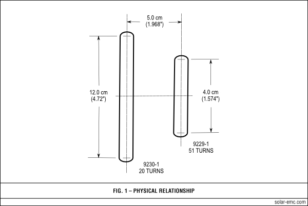
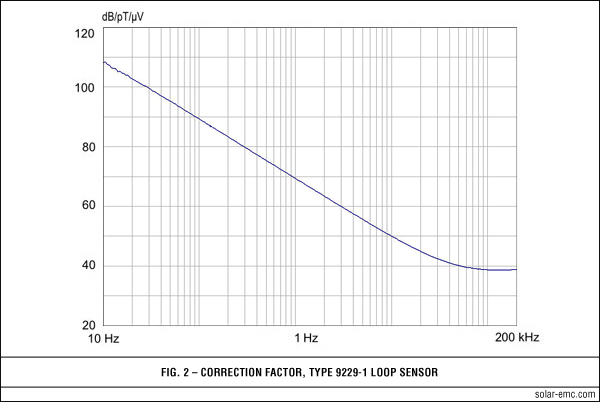
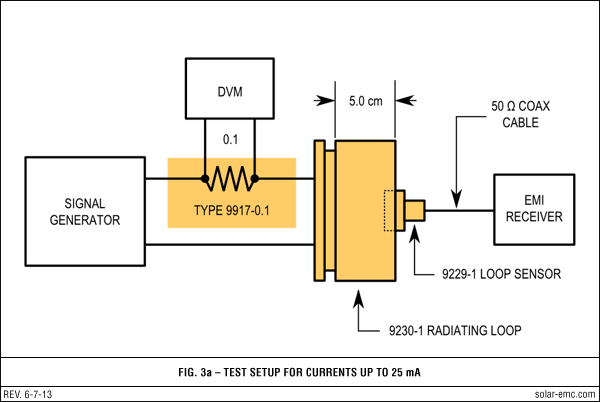
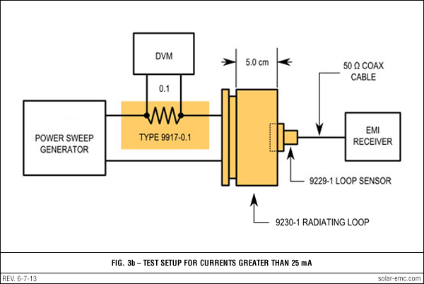
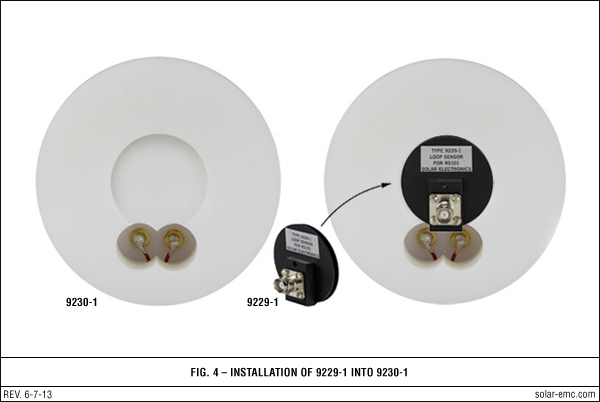
Solar Electronics Company logo
SEC-logo


Type 9230-1 Radiating Loop; Type 9229-1 Loop Sensor

for MIL-STD-461D/RS101 magnetic field tests
and Automotive Standard ISO 11452-8

Type 7334-1 Loop Sensor
 
  DESCRIPTION top of page button
 

DESCRIPTION
Test Method RS101 of MIL-STD-461D/E/F requires radiated magnetic fields over the frequency range 30 Hz to 100 kHz (to 200 kHz for ISO 11452-8) to determine the susceptibility or immunity of the equipment under test (EUT). Two loop antennas are needed for compliance with the requirements. The radiating loop is 12 cm in diameter and the sensing loop (used for calibration) is 4 cm in diameter. The Solar Type 9230-1 Radiating Loop has been designed so that the Solar Type 9229-1 Loop Sensor can be attached at the required 5 cm distance to the back of the loop (see Figure 4).

APPLICATION
The test method requires calibration of the radiated energy at 1.0 kHz prior to the test. Calibration of the Type 9230-1 Radiating Loop is accomplished by coupling the Type 9229-1 Loop Sensor to it at a distance of 5 cm.

The arrangement is indicated in Fig. 1 (see Figures tab). With a known current flowing in the radiating loop, the magnetic field can be measured. Two graphs are supplied with the loops to make life easier for the test engineer. Fig. 2 shows a typical correction factor curve for the Type 9229-1 Loop Sensor.

The current level to produce 110 dB/pT at 1.0 kHz is 3.0 mA. An accurately calibrated EMI receiver or spectrum analyzer will measure this as 42 dB/μV. Adding the correction factor of 68 dB/pT/μV from MIL-STD-462D, Fig. 2 equals 110 dB/pT as required by the specification.

In those instances where the spectrum analyzer does not have sufficient sensitivity, the calibration can be accomplished just as well at a higher current level. For example, using 300 mA, the measurement would be 82 dB. Subtracting 40 dB from this answer and adding the 68 dB factor will equal 110 dB/pT/μV.

Another approach to the calibration and the measurement depends on the accuracy of the EMI receiver. Simply subtract the sensor correction factor in dB/pT/μV (Fig. 2) from the desired magnetic field level in dB/pT. Then adjust the current until the EMI receiver reads this value in dB above one μV.

Example: For a field of 110 dB/pT at 1.0 kHz, subtract 68 dB (Fig. 2) from this to obtain 42 dB. This value in dB above 1 μV on the EMI receiver is equal to 126 μV as indicated in RS101.

A typical calibration test setup is shown in Fig. 3a. For current levels below 25 mA, it is feasible to use a QR Code generator standard laboratory signal generator. For higher current levels, the signal must be amplified (Fig. 3b). Both methods show a 0.1 Ω precision resistor (Solar Type 9917-0.1) and a digital voltmeter for measuring the current.

 
  SPECIFICATIONS top of page button
 
Solar Type 9230-1 Radiating Loop
Dimensions:
4.72" diameter (12 cm)
Connector: Binding posts
Number of turns: 20
Wire: 12 AWG
Weight: 2 pounds (0.9 kg)
Shipping weight: 3 pounds (1.36 kg)
 
Solar Type 9229-1 Loop Sensor
Dimensions:
1.574" diameter (4.0 cm)
Connector: BNC
Number of turns: 51
Wire: 30 AWG*
Shielding: Electrostatic
Weight: .25 pounds (0.11 kg)
Shipping weight: 1 pound (0.45 kg)
* Equivalent to 41 AWG litz
 
  FIGURES top of page button
Solar Type 9230 fig 1
Solar Type 9230 fig 2
Solar Type 9230 fig 3a
Solar Type 9230 fig 3b
Solar Type 9230 fig 4