Solar Electronics Company logo
SEC-logo

Type 7334-1 Loop Sensor

for RE01 and RE101 magnetic emission tests
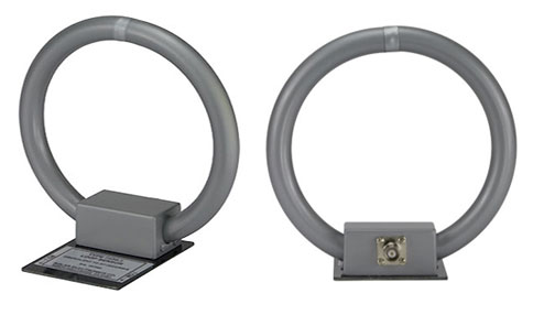
Type 7334-1 Loop Sensor
  DESCRIPTION top of page button

HISTORICAL NOTE
The AT-205/URM-6 loop sensor described in Test Method RE01 of MIL-STD-462 is one of the antennas designed for use with the Navy AN/URM-6B and Stoddart NM-10A receivers. These were the low frequency EMI meters that, in 1948, initiated the emphasis on EMI by the military departments and created the technical discipline we now know as Electromagnetic Compatibility.

DESCRIPTION
The Solar Type 7334-1 Loop Antenna was originally designed as a substitute for the AT-205/URM-6 antenna and is a replacement for Eaton Model 94607-1 as specified in RE01 of MIL-STD-461A. It continues to be used for Test Method RE101 of MIL-STD-461F.

The Type 7334-1 Loop Antenna is equipped with an epoxy-glass base plate which serves as a spacer to enable the user to place the loop at exactly 7 cm from the face of the item under test as required by Test Method RE101 of MIL-STD-461F.

APPLICATION
Connection to the loop is through a BNC connector which enables coaxial cabling to the EMI receiver. The loop is supplied with a correction factor graph (see Figures tab) showing the values in dB which must be added to the reading of a 50 Ω EMI meter to obtain answers in either dB/µV/m or dB/pT. The correction factor decreases as frequency increases from 30 Hz up to approximately 15 kHz, where the factor levels off and remains relatively constant up to 5 MHz.

The Type 7334-1 is required by Test Method RE01 in Parts 2 through 6 of MIL-STD-461C and RE101 of MIL-STD-461D/E/F. These portions of the specification require magnetic field emission tests of cables, equipments, systems and sub-systems installed in, or used in, all phases of military vehicles, ships, submarines, aircraft (including helicopters), spacecraft, or ground-based operations.

TEST METHODS RE01 and RE101
The Type 7334-1 is positioned 7 cm from the face of the equipment under test with the plane of the loop parallel to the equipment face. The best position to begin with is opposite or near a joint or seam.

The associated EMI receiver is then scanned over the range 30 Hz to 100 kHz searching for emissions. At the frequencies where emissions are found, the loop antenna is moved about the surface seeking the strongest emission level. When a strong signal is detected, the loop is oriented on its axis for a maximum reading.

This procedure is repeated for all surfaces of the equipment under test. Although the specification is not clear on the point, it appears to indicate that all six sides (including the bottom) of a piece of equipment must be tested in this manner.

QR Code generator

When testing cables, the loop antenna is placed 7 cm from the cable with the plane of the loop parallel to the cable. The nonmetallic base plate of the Type 7334-1 provides a convenient means for establishing the correct 7 cm distance.

 
  SPECIFICATIONS top of page button
spacer
Dimensions: 5.24" diameter (13.3 cm)
Connector: BNC
Number of turns: 36
Wire: DC resistance between 5 and 10 Ω
Shielding: Electrostatic
Weight: 2 pounds (0.9 kg)
Shipping weight: 3 pounds (1.36 kg)
 
  FIGURES top of page button
spacer
7334-1 waveform chart
 
Product List
♦ Antennas
♦ Application Information
♦ Capacitors
♦ Coupling Networks
♦ Generators
♦ Line Impedance Stabilization Networks
♦ MIL-STD-461 Equipment List
♦ Probes
♦ Resistive Devices
item # page links
♦ Transformers
♦ Miscellany