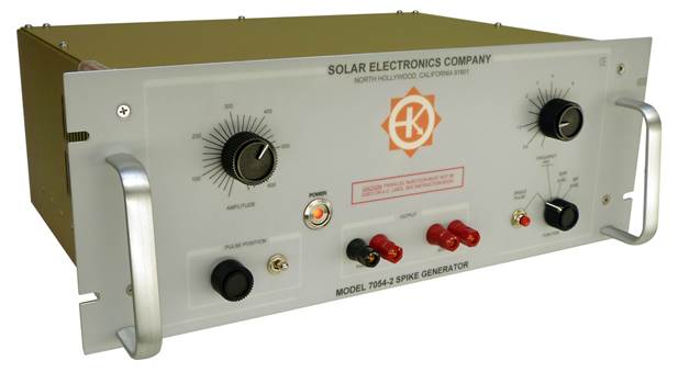
Solar Electronics Company logo
SEC-logo

Model 7054-2 Spike Generator 600 V

for conducted transient susceptibility testing up to 600 V peak
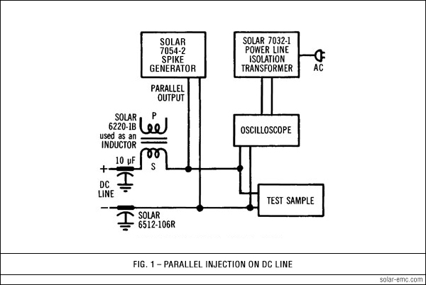
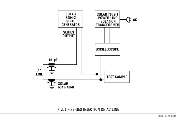
Type 7054-2
 
  DESCRIPTION top of page button

SOLAR SPIKE GENERATOR UPDATE
Effective April 2017, we are assigning new part numbers to our Solar Model 7054 line of spike generators and will no longer be manufacturing the Solar Model 7054-1, -1A or -1B lines.

We are now offering the Solar Model 7054-2 Spike Generator, as well as Solar Models 7054-2A and -2B, to continue assisting your testing to Method CS06 of MIL-STD-462, Method 5006.1 of MIL-STD-826A, various missile specifications and other requirements. The Model 7054-2 may also still be used to perform Section 17 testing of RTCA/DO-160G as described below on this page.

In short, the specifications, functionality and performance of these updated generators are exactly the same.

Why the change? Solar Electronics Company designed and has been manufacturing our Model 7054-1 line of generators since 1970.

Over the years, parts have become harder to find or even obsolete. To continue to provide these quality EMC generators, we redesigned the internal circuitry and updated components. This redesign prompted the part number changes and will result in improved reliability, ease of service and better availability of parts.

What hasn’t changed: there will be no discernible difference to you, the end user. These generators meet the same specifications with the same performance you have trusted for so many years.

For those who have graduated from the 50 V and 100 V spike susceptibility category, we offer this high-power 600 V transient generator. The Solar Model 7054-2 Spike Generator delivers over 300 kW into low resistance loads. It has the flexibility and capability of the previous models, including the ability to shift the transient in phase to any position on the sine wave of the AC line feeding the test sample. The amplitude and the repetition rate are adjustable.

APPLICATION
The Model 7054-2 was especially designed for screen room use in applying high voltage transients at power line inputs to electronic equipment. The adjustable amplitude makes it possible to determine the threshold of susceptibility to spikes appearing on the power line. The Model 7054-2 may be used for performing tests per Method CS06 of MIL-STD-462, Method 5006.1 of MIL-STD-826A, various missile specifications and others. The Model 7054-2 also may be used to perform Section 17 testing of RTCA/DO-160G when used in conjunction with Solar Type 2201-1, 2201-2 and 2201-3 Impedance Matching Transformers.

DESCRIPTION
The peak amplitude of the Solar Model 7054-2 is adjustable from 10 V to over 600 V into 5 Ω. The source impedance is less than 0.5 Ω. The transient shape approximates the curve given in Figure 19 of MIL-STD-462 with less than or equal to 2.0 µS rise time and approximately 10 µS fall time.

On 50, 60 or 400 Hz power lines the transient can be applied in a periodic manner to the negative or the positive half-cycle of the power frequency. The transient's relation to the sine wave may be adjusted in phase from 0° to 360°. For non-synchronous injection on either AC or DC lines, the repetition rate can be adjusted from 0.8 pulse per second to 10 pulse per second. Single transients can be applied with the pushbutton on the panel.

Two sets of output terminals allow either parallel or series injection into the power line. Series injection is used on AC lines. Parallel injection is used on DC lines. The output winding used for series injection can carry 25 A of power current. The output terminals are isolated from the chassis and the power cord.

FEATURES
Provides output levels from 10 V to 600 V into 5 Ω. Delivers more than 300 kW peak into 0.5 Ω load
Adjustable pulse position on AC lines relates the transient susceptibility to real time aspects of digital systems
Single pulse feature for controlled isolation of transient effects
Output terminals for series or parallel injection
Standard rack panel construction: 19" wide x 7" high x 12.75" deep
(48.26 cm x 17.78 cm x 32.38 cm)
QR Code generator
 
  SPECIFICATIONS top of page button
spacer
Spike amplitude: Continuously adjustable from less than 10 V to 600 V peak
Repetition rate: Continuously adjustable from 0.8 to 10 pulses per second
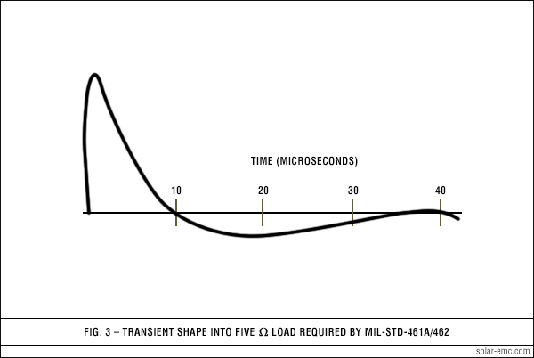
Rise time: Less than or equal to 2.0 µS into 5 Ω resistive load
Spike duration: Output falls to zero in approximately 10 µS
Spike shape: See Figure 3. Similar to Figure 19 of MIL-STD-462
Phase adjustment: Spike position adjustable from 0° to 360° periodically on 50, 60 or 400 Hz sine wave
Internal impedance: Less than 0.5 Ω
Output power: More than 300 kW peak into 0.5 Ω load
Power current in series injection mode: Handles up to 25 A of current at power frequencies
Power requirements: 115 V 60 Hz, 1.6 A (230 V 50 Hz, 0.8 A available)
Dimensions, standard rack panel: 19" wide x 7" high x 12.75" deep
(48.26 cm x 17.78 cm x 32.38 cm)
Weight: 28 pounds (12.7 kg)
Boxed weight (approx.): 36 pounds (16.33 kg)
spacer
  FIGURES top of page button
 
7054-1 FIG 1
 
7054-1 FIG 2
 
7054-1 FIG 2
 
  USEFUL ACCESSORIES top of page button
spacer

Solar Type 2201-1 Impedance Matching Transformer Plugs into SERIES output terminals of Model 7054-2 to provide a 50 Ω source capable of 200 V to 600 V open circuit per RTCA/DO-160G, Section 17 Category A

Solar Type 2201-2 Impedance Matching Transformer Plugs into SERIES output terminals of Model 7054-2 to provide a 50 Ω source capable of 200 V to 1000 V open circuit per RTCA/DO-160G, Section 17

Solar Type 2201-3 Impedance Matching Transformer Plugs into SERIES output terminals of Model 7054-2 to provide a 50 Ω source capable of 56 V to 200 V open circuit per RTCA/DO-160G, Section 17 Category B

 
  SPECIAL MODELS top of page button
spacer

Solar Model 7054-2A
Waveshape falls to zero in approximately 50 µS. Provides 400 V peak into 5 Ω load. Handles 15 A power current.

Solar Model 7054-2B
Waveshape falls to zero in approximately 120 µS. Provides 400 V peak into 5 Ω load. Handles 10 A power current.