

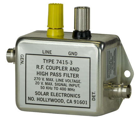
Type 7415-3 RF Coupler and High Pass Filter |
|
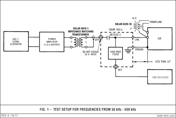
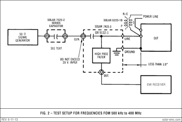
There are those who disagree with the RF conducted susceptibility test setup of Method CS02 of MIL-STD-462. Homemade rigs have sprouted to comply with the coupling capacitor requirement, each with its own disadvantage. Our little Solar Type 7415-3 RF Coupler is the answer. A neat little box with BNC connectors and a pair of binding posts, it is rated at 270 VAC at the LINE terminals and 20 V RMS into the GEN port. It looks good and does a fine job. The test setup diagram of the specification will result in power frequency voltages at the voltmeter terminals. If an untuned voltmeter is used, it is difficult to measure a 1 V RF signal in the presence of the AC line voltage. It is not practical to use an EMI receiver for this, unless the Solar Type 7415-3 is placed in series with it. Otherwise, the power frequency voltage can damage the input circuit of the EMI receiver. The Type 7415-3 contains a high pass filter in series with the detector circuit to eliminate power frequency voltages and allow RF signals from 50 kHz to 400 MHz to pass to the EMI receiver as required. The high pass filter consists of three stages of an RC network using series capacitors and shunt resistors. Using resistors instead of inductors enables the unit to cover a wide frequency range, with a 40 dB insertion loss in the pass band. This makes it necessary to multiply the detected voltage by a factor of 100 (-40 dB) for the measurement of the injected voltage. The series capacitor in the Type 7415-3 consists of several styles of capacitors in parallel. Mica, ceramic and wrapped capacitors exhibit different characteristics versus frequency and the combination eliminates the need to change the value of the capacitor as frequency changes from 50 kHz to 400 MHz. A tuned voltmeter such as an EMI receiver is recommended as the detector for further isolation of unwanted frequencies, such as harmonics of the signal generator. If the generator waveform is "clean," an untuned meter can be used if it is terminated in 50 Ω and preserves a 50 Ω coaxial circuit throughout the frequency range. The reactance of the built-in series capacitor from the generator to the power line terminal presents very little loss at 50 kHz. At 400 Hz its reactance is about 362 Ω. Therefore, it represents a path by which 400 Hz power voltages can be fed back to damage the output circuit of the signal generator. To avoid this, one suggestion is to use an isolating transformer at the output of a low impedance signal source. Figure 1 shows the use of a power amplifier and the Solar Type 8810-1 Impedance Matching Transformer. This arrangement can be used for injection levels up to 20 V RMS from 50 kHz to 500 kHz with satisfactory results. At frequencies above 500 kHz, we recommend that a 50 Ω signal generator be used as indicated in Fig. 2 except that a small capacitor must be connected in series between the generator and the Type 7415-3 RF Coupler.
The Solar Type 7525-2 is 0.1 µF series capacitor, fitted with BNC connectors.
The reactance of this series capacitor reduces the power frequency voltage to a safe limit so that the output circuit of the generator will not be damaged. At 500 kHz, the RF signal is not greatly attenuated.
At frequencies above 20 or 30 MHz, the connections from the banana jacks to the test sample will create discontinuities that cannot be removed from the setup. It is recommended that the wires from the banana jacks be less than 1" long (25.4 mm) to minimize VSWR anomalies.
SOLAR TYPE 9132-1 RF COUPLER AND HIGH PASS FILTER |
|
| Type 7415-3 Dimensions: 2.0" wide x 2.5" high plus mounting flanges x 1.25 deep" (51 mm x 63.5 mm x 31.25 mm) |
| Type 9132-1 Dimensions: 2.88" wide x 3.06" high x 2.0" deep plus mounting flanges (73 mm x 78 mm x 51 mm) |
 |
|