Solar Electronics Company logo
SEC-logo

RFI/EMI Current Probes and Injection Probes
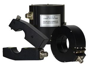
 
  DESCRIPTION top of page button

CURRENT PROBES
Current probes required by various EMI specifications (such as MIL-STD-461/2) are toroidal transformers designed to measure RF currents on active power lines or other conductors.

APPLICATION
A current probe is used as a “pick-up” device for measuring RF current in single conductors or cable bundles when connected to the 50 Ω input
of a radio frequency interference measuring receiver or spectrum analyzer.

DESCRIPTION
Direct connection to the conductor carrying EMI current is not necessary, since the probe may be opened for insertion of the conductor into the window of the toroid and then closed again to form a toroidal transformer with the conductor acting as a one-turn primary.

A correction factor graph is provided to convert measured µV to EMI µAs. When the EMI current is measured in dB above 1 µV as indicated on a conventional EMI meter, the correction factor will convert the measurement to dB above 1 µA. The correction factor is the inverse of the transfer impedance, Zt. Each probe is shipped with a graph of the correction factor versus frequency, keyed to the serial number on the probe.

INJECTION PROBES
Specifications require the injection of large high frequency currents into cable bundles and individual wires, using inserted secondary toroidal transformers placed around the conductors being tested.

APPLICATION
High power RF amplifiers with 50 Ω output impedance are used to deliver voltage to the injection probe. The wire or cable through the window of the probe acts as a secondary of the toroidal transformers. This test method is intended to be used instead of earlier methods, such as CS-01, CS-02, and RS-02 of MIL-STD-461.

DESCRIPTION
Bulk current injection probes are available in two styles:
1. Fixed window style where the wire(s) under test must be passed through the window.
2. A split toroidal design where the probe can be opened up and clamped over the wire(s) under test.

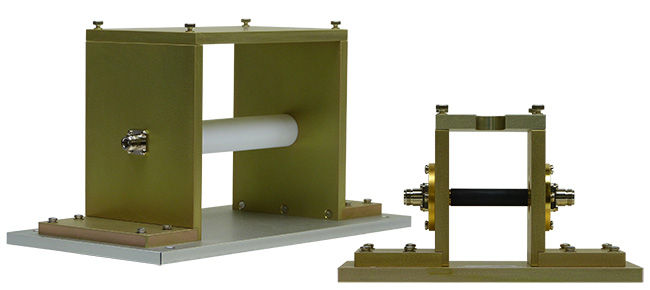
Each probe is calibrated for insertion loss and transfer impedance in a test fixture designed for the particular window size. This fixture provides a signal path with a low Voltage Standing Wave Ratio (VSWR). A typical fixture is Solar Type 9125-1, used for probes with 32 to 44 mm diameter windows. Ask for details on this and other test fixtures.

Injection probes currently available are described later in this section. Development of new styles is ongoing. If a probe meeting your requirements is not found on the list, send us details and we will provide a solution.

TECHNICAL INFORMATION
Current probes used as receptors are known as “inserted primary toroidal transformers” for connection to EMI receivers. Injection probes which deliver high RF currents into wires through the window are called “inserted secondary toroidal transformers”.

The maximum voltage carried on wires through the window is limited only by the insulation of the wires. Maximum primary current in the wires through the window of current probes is listed in the table in the Specifications tab (symbol lp).

The signal input to injection probes is rated in W from the signal source as indicated in the table in the Specifications tab.

Development is continuing on new and useful probes, both current measuring sensor probes and high wattage injection probes. The following is a partial list. As time goes on, the list will grow. If you do not see what you need, just ask.

QR Code generator
 
  SPECIFICATIONS top of page button
   
 
CLAMP-ON CURRENT PROBES
  Maximum PRI. (pl) current, A  
 Type number
Window diameter Nominal
ZT Ω
DC to 60 Hz 400 Hz RF (CW) Pulse Frequency range
 9124-1N
1.25" (32.0 mm)
0
.001
200
70
50
5000
1 kHz - 200 MHz
 9205-1
1.25" (32.0 mm)
0
.33
800
800
50
100 20 Hz - 8 MHz
 9118-1
1.25" (32.0 mm)
0
.10
350
150
22
500 500 Hz - 200 MHz
 9134-1
1.25" (32.0 mm)
0
.70
500
400
5
100 20 Hz - 100 MHz
 6741-1
1.25" (32.0 mm)
0
.70
350
225
5
100 10 kHz - 100 MHz
 9207-1
1.25" (32.0 mm)
1
.0
800
450
4
.2
100 20 Hz - 150 MHz
 9209-1
1.25" (32.0 mm)
1
.0
800
800
100
200 20 Hz - 30 MHz
 9145-1
1.25" (32.0 mm)
5
350
350
42
100 10 kHz - 152 MHz
 9123-1N
1.25" (32.0 mm)
1-5
200
200
40
60 10 kHz - 500 MHz
 9214-1
1.25" (32.0 mm)
5
600
600
21
200 20 Hz - 150 MHz
 9215-1N
1.25" (32.0 mm)
1-5
400
350
40
100 20 Hz - 500 MHz
 9231-1
1.25" (32.0 mm)
.010
300
200
7
3000 1 kHz - 200 MHz
 9219-1N
1.25" (32.0 mm)
.025
400
300
150
200 20 Hz - 20 MHz
 9250-1N
1.25" (32.0 mm)
.10
200
200
10
200 10 kHz - 450 MHz
 9257-1N
2.62" (67.0 mm)
4
500
500
200
200 20 Hz - 30 MHz
 9258-1N
2.62" (67.0 mm)
5
500
500
100
200 20 Hz - 100 MHz
 9261-1N
2.62" (67.0 mm)
2
 
500
500
2
.6
100
20 Hz - 200 MHz
 9263-1N
2.62" (67.0 mm)
.03
500
500
80
200 20 Hz - 100 MHz
 9301-1N
2.62" (67.0 mm)
8
350
350
60
200 20 Hz - 500 MHz
 9303-1N
2.62" (67.0 mm)
.001
500
200
100
5000 20 Hz - 100 MHz
 9305-1N
2.62" (67.0 mm)
1
500
500
2
.3
200 20 Hz - 200 MHz
 9306-1N
2.62" (67.0 mm)
.005
800
300
14
5000 1 kHz - 100 MHz
 9307-1N
2.62" (67.0 mm)
.005
300
300
60
5000 20 Hz - 100 MHz
21406-1N 2.62" (67.0 mm)   .01
350
350
40
  2200 100 Hz - 30 MHz
We provide equivalents for most Stoddart and Eaton probes.
 
CLAMP-ON INJECTION PROBES
Insertion loss  
 Type No.
Window diameter Winding
current
Rated W Under 6 dB Under 10 dB Under 15 dB Under 20 dB Frequency range
 9108-1N
1.25" (32 mm) 10 50
120 kHz - 70 MHz 60 kHz - 150 MHz 10 kHz - 200 MHz
 9142-1N
1.50" (38 mm) 50 200 10 MHz - 350 MHz 5 MHz - 430 MHz 2.5 MHz - 500 MHz 1.5 MHz - 500 MHz 2 MHz - 500 MHz
 9144-1N
1.50" (38 mm) 26 100 200 kHz - 8 MHz 70 kHz - 90 MHz 40 kHz - 100 MHz 4 kHz - 100 MHz
 9217-1N
1.50" (38 mm) 26 100 200 kHz - 5 MHz 80 kHz - 100 MHz 50 kHz - 100 MHz 10 kHz - 100 MHz
1.50" (38 mm)             10 kHz - 100 MHz
 9607-1N
1.25" (32 mm) 10 50 500 kHz - 1 MHz 200 kHz - 30 MHz 120 kHz - 300 MHz 10 kHz - 300 MHz
 9719-1N
1.50" (38 mm) 60 200 5 MHz - 100 MHz 3 MHz - 200 MHz 1.5 MHz - 200 MHz 700 kHz - 200 MHz 10 kHz - 200 MHz
 2216-1N
1.50" (38 mm) 26 100 50 kHz - 30 MHz 10 kHz - 100 MHz 1 kHz - 100 MHz
 Injection probes can also be used as current probes. A correction factor graph and instructions for its use are supplied.
 
 
CALIBRATION FIXTURES
 Type No.
Description
 9125-1
 For injection probes, 1.5" (32 mm - 44 mm) diameter window. 20 Hz to 500 MHz. Type N connectors.
 9125-2
 For Solar 9119-1N Probe and similar, 1.25" (32 mm) diameter window. 400 MHz to 3 GHz. Type N connectors.
 9251-1
 For Eaton, Stoddart and Solar probes, 1.25" (32 mm) diameter window. 20 Hz to 500 MHz. Type BNC connectors.
 9254-1
 For Eaton, Stoddart and Solar probes, 2.62 " (66 mm) diameter window. 20 Hz to 500 MHz. Type N connectors.
 9321-1
 For Eaton, Stoddart and Solar probes, 0.75" (19 mm) diameter window, totally enclosed. 20 Hz to 1.5 GHz. Type BNC  connectors.
 9330-1
 For Eaton, Stoddart and Solar probes, 1.25" (32 mm) diameter window, totally enclosed. 20 Hz  ≈ 1. GHz. Type N connectors.
 2925-1
 Fixtures for Solar Type 9335-2 Probe. 20 Hz to 100 MHz. Type N connectors. (9357-1 has been discontinued
 NOTE: Except for Type 9125-1 and 2925-1, the probes are supported and centered in the fixture.