

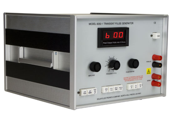
Model 8282-1 Transient Pulse Generatorfor conducted transient susceptibility testing,
|
|
|
APPLICATION DESCRIPTION
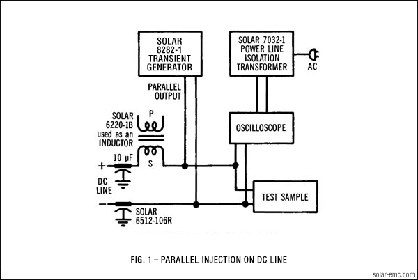
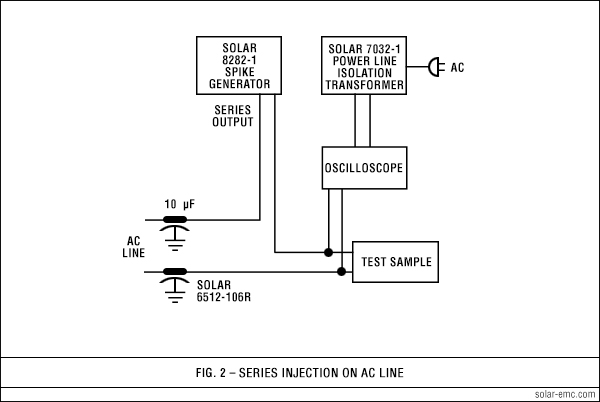
Three different spike durations are provided: 0.15 µS, 5.0 µS, and 10.0 µS. The pulse shape approximates the curve of Figure 1 in MIL-STD- 462. The amplitude of the spike voltage is fully adjustable and is displayed on a digital meter. Two sets of output terminals allow either parallel or series injection into the power line. Series injection is used on AC lines. Parallel injection is used on DC lines. The output winding used for series injection can carry 25 A of power current. The output terminals are isolated from the chassis and the power cord. The repetition rate of the spike can be adjusted with a panel control to any rate from 0.5 to 50 pulse per second. A single pulse can be injected with the aid of a panel-mounted pushbutton. All functions are selected by pushbuttons which are lighted when activated. The Solar Model 8282-1 Transient Pulse Generator provides up to 600 V peak amplitude for each of the 0.15, 5.0 and 10.0 µS spikes. The output voltage rises steeply to peak amplitude as adjusted by the panel control, then falls exponentially to cross through zero at the duration of 0.15, 5.0, or 10.0 µS as selected by pushbuttons. The voltage falls below zero and "rings" for a period determined by the inductance in the output circuit or the load.
With series injection on 50, 60 or 400 Hz power lines, the spike can be applied to either the positive or negative half cycle of the power frequency sine wave. The spike can be adjusted to fall on the power sine wave from 0º to 360º . For non-synchronous injection,
the repetition rate can be adjusted from 0.5 to 50 p.p.s. Two methods of remote triggering are provided. One method requires the application of 24 V DC to trigger the pulse at rates determined by an external switch up to 50 pulse per second. The second method requires the application of a square wave which can be used to trigger the spike up to 50 pulse per second for the 0.15 µS spike and up to 1000 pulse per second for the 5.0 and 10.0 µS spikes. This latter feature can be used to trigger the spike in sync with some function within the equipment under test.
|
|||||||||||||||||
|
|
|||||||||||||||||
| Spike durations: Pushbutton selectable durations of 0.15 µS, 5.0 µS and 10.0 µS (±20%) to zero crossover, into 5.0 Ω resistive load |
| Adjustable peak amplitude: Up to 600 V for 0.15 µS, 5.0 µS and 10.0 µS durations into 5 Ω non-inductive load |
| Internal impedance: Less than 5.0 Ω for 0.15 µS, less than 2.0 Ω for 5.0 µS, less than 1.0 Ω for 10.0 µS |
| Pulse repetition rate: Manually adjustable up to 50 pulse per second for all pulse durations |
| Pulse shape: Ringing characteristic similar to Figure 19 in MIL-STD-462 when connected to non-inductive load |
| Pulse position: Adjustable from 0° to 360° on 50 Hz, 60 Hz or 400 Hz power lines |
| External sync operation: Remotely triggerable up to 50 pulse per second for 0.15 µS, up to 1000 pulse per second for 5.0 and 10.0 µS |
| Amplitude display: Panel meter is a digital display of peak amplitude as it would be into a 5 Ω resistive load |
| Power current in series injection mode: Handles up to 50 amperes of EUT current at power frequencies |
| Power requirements: 115 V 60 Hz, 3.0 A (230 V 50 Hz, 1.5 A available) |
| Dimensions: 12.25" wide x 8.7" high x 13" deep (311 mm x 211 mm x 330 mm) |
| Weight: 30 pounds (13.6 kg) |
 |
 |
| Solar Type 6220-1B Audio Isolation Transformer |
| Solar Type 6512-106R 10 µF Feed-Thru Capacitor |
| Solar Type 7032-1 Isolation Transformer |
| Solar Type 8282-150 Transient Pulse Transformer Plugs into SERIES output terminals. Handles up to 150 A through the secondary for high current test samples. |
| Solar Type 8525-1 Non-Inductive 5 Ω Load |