

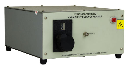
Model 9554-( ) Variable Frequency Modulesfor use with Model 9354-1 or 9354-2 Transient Generator
|
|
APPLICATION DESCRIPTION
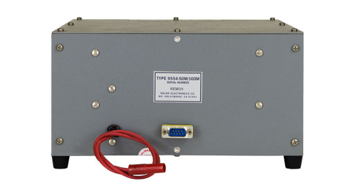
Two cables connect the module to the Model 9354-1 or Model 9354-2. One cable is a single insulated wire to carry high voltage DC to the module. The other cable delivers low voltage DC to the module for operation of relays. OPERATION With the selected module connected, the charge voltage of the module is adjusted by the AMPLITUDE control on the Model 9354-1 or Model 9354-2 Transient Generator. The AMPLITUDE knob is marked in percentage of the available charge voltage for the module being used. The amplitude and frequency of the damped sinusoidal wave into the load can be determined by an associated oscilloscope with a 50 Ω input. After the charge voltage is adjusted to the desired value, the damped sinusoidal wave is applied to the load by pushing the button on the module.
|
|||||
|
|
|||||
| Dimensions: 10" wide x 5" high x 12" deep (25 cm x 12.7 cm x 30.48cm) |
| Weight: 10-12 pounds (4.5-5.5 kg)* |
| * Varies with model |
| Solar Type 9125-1 Calibration Jig |
| Solar Type 9142-1N Injection Probe |
| Solar Type 2925-1 Calibration Jig |
| Solar Type 9335-2 Multiple Impedance Coupling Device |
| Solar Type 9410-1 High Voltage Attenuator The input to the Type 9410-1 can be used for a 50 Ω coaxial load |
| Solar Type 9841-1 1000 V Termination 50 Ω coaxial 1 W average power. Typical input VSWR in a 50 Ω system under 1.5 from DC to 1 GHz. |